
Hawaii DOT Single-Flared Buried-in-Backslope Guardrail End Terminal – Reverse Direction Test
Report Number(s): TRP-03-496b-25
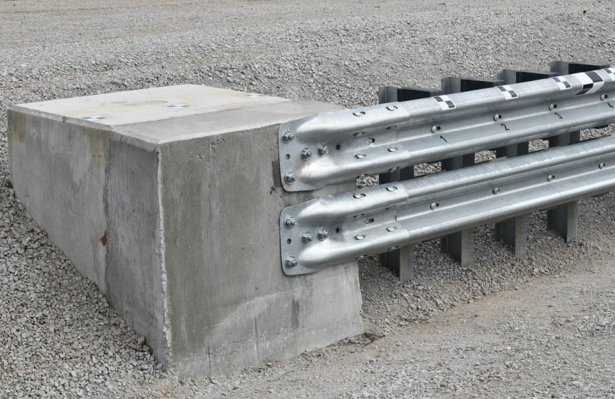
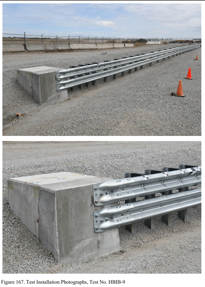
Description: Hawaii DOT typically uses two configurations of a flared buried-in-backslope system design. The first configuration consists of a single flare extending from the tangent guardrail system, terminating at a rigid anchor block. The second configuration utilizes a secondary flare at adjacent to the end anchorage. The primary flare of the rail has flare rates selected based on the design speed of the barrier system and roadway, whereas the secondary flare is fixed at 7.4:1 with respect to the tangent roadway. A full evaluation was performed with MASH test designation nos. 3-32, 3-33, 3-34, 3-35, and 3-37a and 3-37b on the HBIB system with dual-flare configuration. The dual flare was most severe for standard traffic direction crashes, but would be less severe when used in trailing-end or reverse-direction crashes. This was because the secondary flare of the dual-flare system had a larger flare rate away from the roadway. For standard-direction impacts, the secondary flare rate contributes to a higher effective impact angle; for reverse-direction impacts, the secondary flare decreases the effective impact angle. Thus, the single-flare configuration was believed to be more severe in reverse-direction configurations. The system was modified to represent the single-flare configuration. This was accomplished by extending the transition post nos. 1 through 8 with the single-flare configuration (4.4-degrees or 13:1), and placing the anchor block adjacent to the bottom toe of the V-ditch. The resulting system had a 13:1 flare rate between the anchor block and post no. 29. The same reinforced concrete block was used for the single-flare configuration as was used for the dual-flare configuration. To accommodate the difference in anchor positions, a built-up “cap” was added to the front face of the concrete anchor block so that the rail would be terminated at the block and in line with the single flare. The cap consisted of a trapezoidal shape, as shown in Figure 145 measuring 12¾ in. on the downstream side and 14½ in. thick on the upstream side. Note that for purposes of this discussion, downstream refers to nominal travel direction, not the direction of reverse-direction impact. The trapezoidal cap was doweled into the face of the existing concrete anchor block with bent no. 4 bars and epoxied to a depth of at least 6 in. Additionally, researchers selected post-installed attachments to secure the W-beam end shoe to the reinforced cap instead of cast-in ferrule assemblies. All other system details were the same for the single-flare configuration evaluated during test no. HBIB-9. The system installation for test no. HBIB-9 is shown in Figures 132 through 169, and material specifications, mill certifications, and certificates of conformity for the system materials are provided in Appendix D
Test Level: 3
System Type: BIB Guardrail End Terminal
MASH Test Number: 3-37a
Proprietary/Non-proprietary: Non-proprietary
Pass/Fail: Fail
Evaluation: Full-Scale Crash Testing
Sponsor: Hawaii Department of Transportation
Test Article Description
Aesthetic: No
Location: Upstream Terminal
Report(s):
 Back
Back