
Final Report Link: Development of Field Applied Fittings for Wired Rope Barrier and Conversion to High Tension
| TTI Research Supervisor: D. Lance Bullard, P.E. Texas Transportation Institute Texas A&M University System TAMU 3135 College Station, Texas 77843-3135 (979) 845-6375 [email protected] |
Pooled Fund Technical Representative: Jeffery K. Petterson, P.E. Design Policy & Strategic Analysis Estimating Manager Roadside Safety Engineer Washington State Department of Transportation (WsDOT) P.O. Box 47329 Olympia, WA 98504-7246 (360)705-7278 [email protected] |
The objective of this project was to identify and test a new field application method for wire rope terminations. The project also developed a procedure for converting the low tension wire rope systems to a higher tension system. Performance of the terminations and the higher tension system were verified through a full scale crash test.
Six products were reviewed by the project technical representative, of which the pooled fund technical representative selected three sample products for additional testing. The products selected demonstrated the highest probability of maintaining a permanent connection to the 3×7 wire rope under dynamic loading conditions. Nucor Steel Marion, Inc. provided funding to test their product alongside the others selected.
Each of the four wire rope termination products considered was subjected to static and dynamic loads to investigate potential failure modes. In addition, testing was performed to determine the strength of the connections under static and impulse loads.
The Field Swage termination and the Epoxy Socket performed the best under dynamic and static loading conditions. Both terminations provide the full strength of the connected wire rope when properly installed.
The researchers recommend the Field Swage termination be used as the retrofit for low tension applications. This product is quicker and simpler to attach than the Epoxy Socket Termination and provides higher dynamic and static capacities than the selected mechanical terminations.
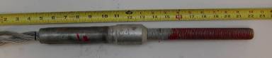
Field Swage Termination
Crash Testing
The full scale test installation was 476 ft long and consisted of 336 ft of modified “Weak-Steel Post Wire Rope Guardrail System SGR01a-b” with a high-tension terminal on each end. Wire rope heights were the same as detailed in the SGR01a-b specification. The system was terminated with Trinity CASS terminals that utilize Cable Release Posts (CRP). To match field applications Standard 3×7 non-prestretched wire ropes were used. A splice connection was placed midspan between support posts 24 ft downstream of first contact with the test vehicle at post 13.
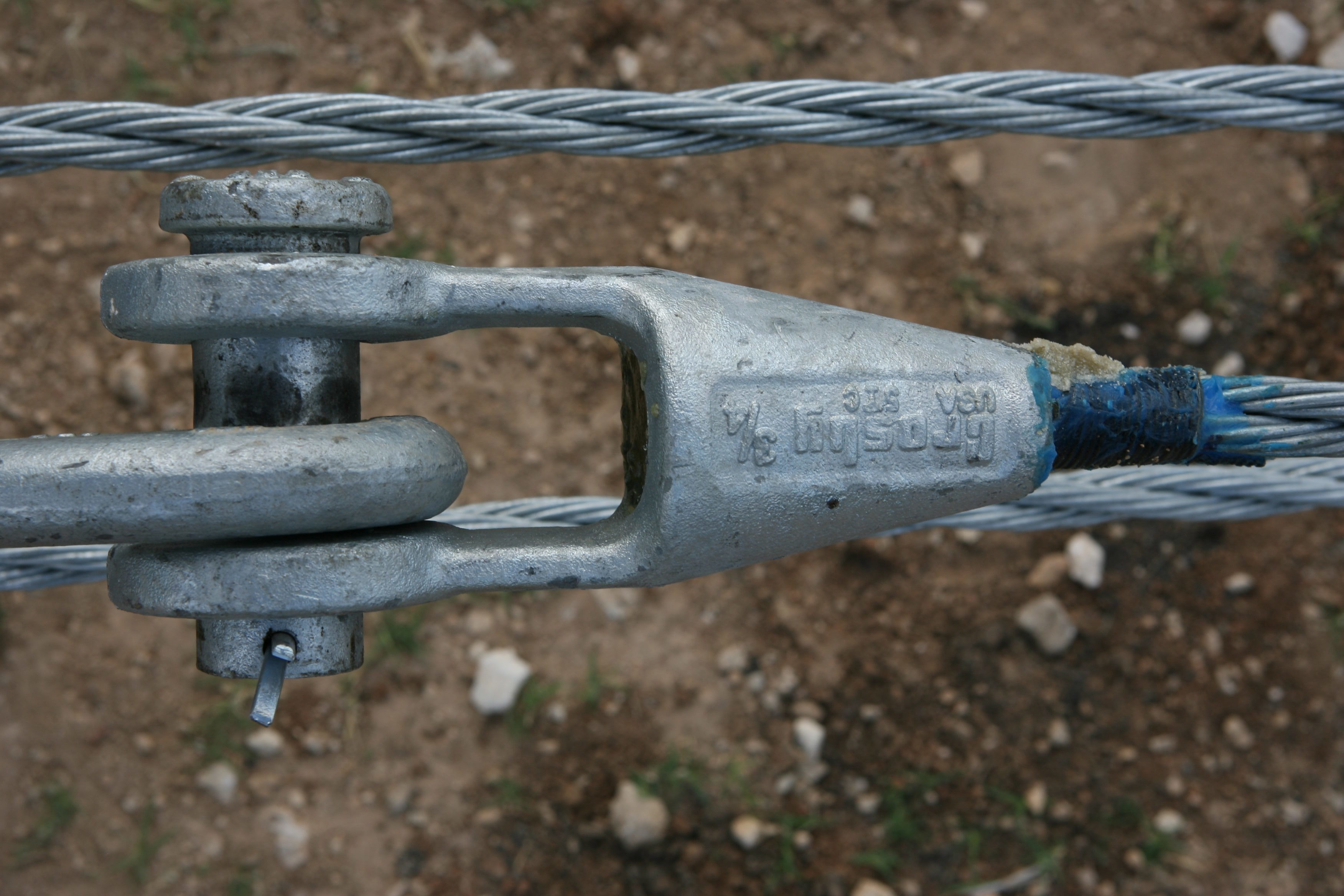
A Crosby 3/4-inch G-416 epoxy socket was used for termination of each wire rope. The epoxy socket termination provides the same capacity as the field swage termination. However, this termination was considered more critical than the field swage because it presented an increased potential for vehicle snagging. It was concluded that if the epoxy socket termination was successful then the field swage would also be successful. Each epoxy socket requires 86 cc of Crosby Wirelock W416‑7 socket compound. A standard Crosby HG-226 1-inch x 12-inch eye and eye turnbuckle were used to connect the two epoxy sockets at each splice. A 1‑inch x 6-inch Crosby G-291 eye bolt with double nuts was used to terminate the wire ropes at the CRP. The wire ropes were tensioned between 5620‑5640 lb for the full-scale crash test.
The modified low-tension wire rope barrier system contained and redirected the 2000P vehicle. The vehicle rode over the top and bottom wire ropes, which were under the vehicle as it came to rest. Maximum dynamic deflection during the test was 10.2 ft. The ropes detached from some of the posts, however, no loose posts or other debris were present to penetrate or show potential for penetrating the occupant compartment, or to present hazard to others in the area. Maximum occupant compartment deformation was 2.2 inches laterally across the floorpan. The 2000P vehicle remained upright during and after the collision event. The 2000P vehicle came to rest within the barrier system and did not intrude into adjacent traffic lanes. Longitudinal occupant impact velocity was 6.9 ft/s (2.1 m/s), and longitudinal ridedown acceleration was -16.4 g’s. The vehicle did not exit the system.
 |
 |
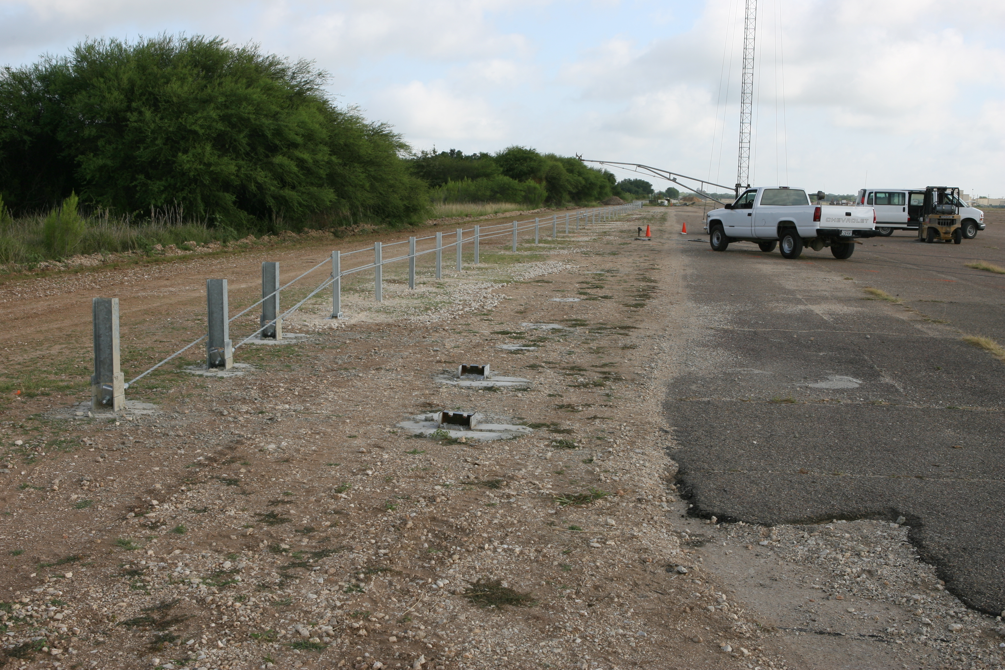
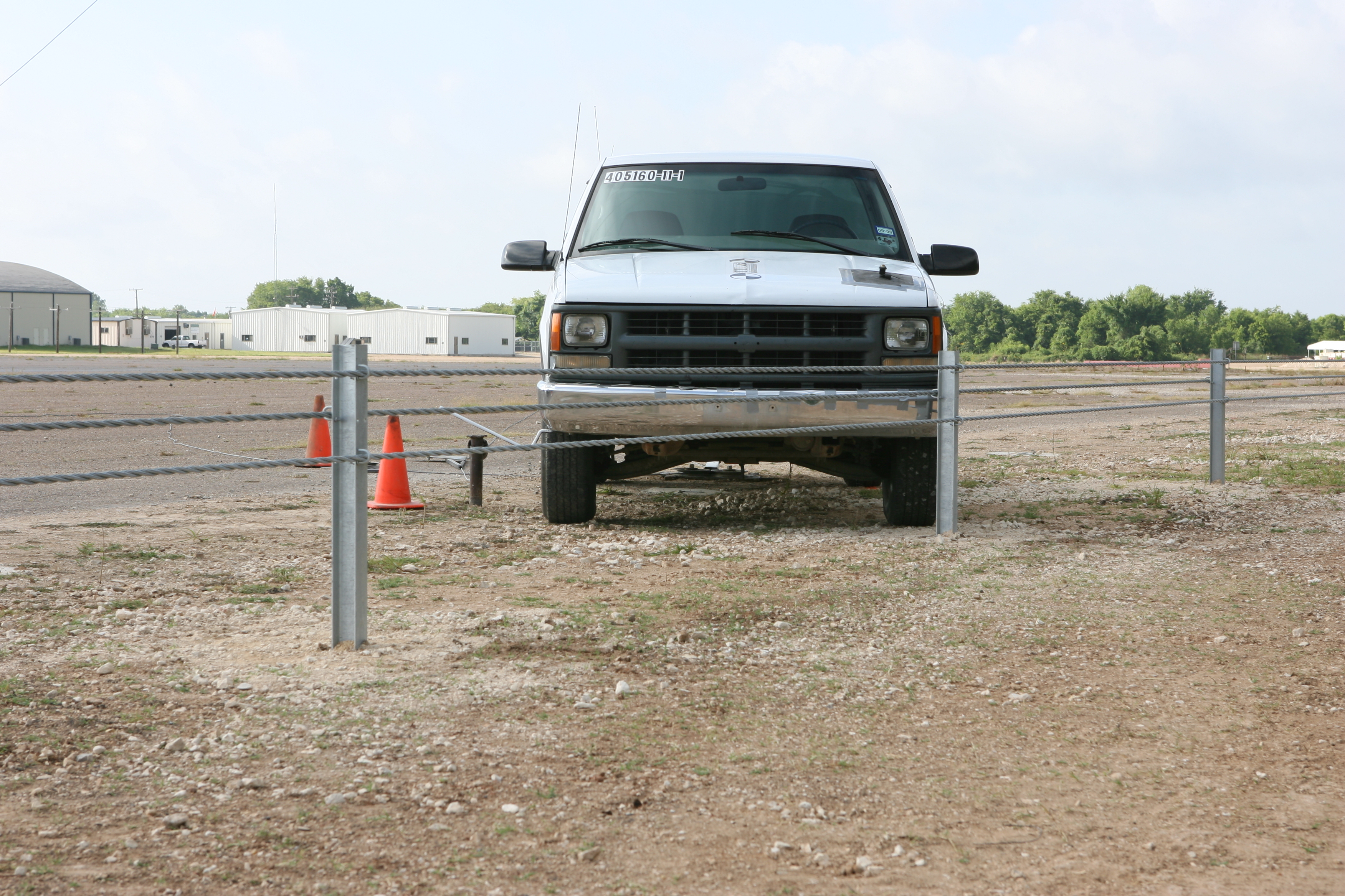
| Barrier Before Test | |
 |
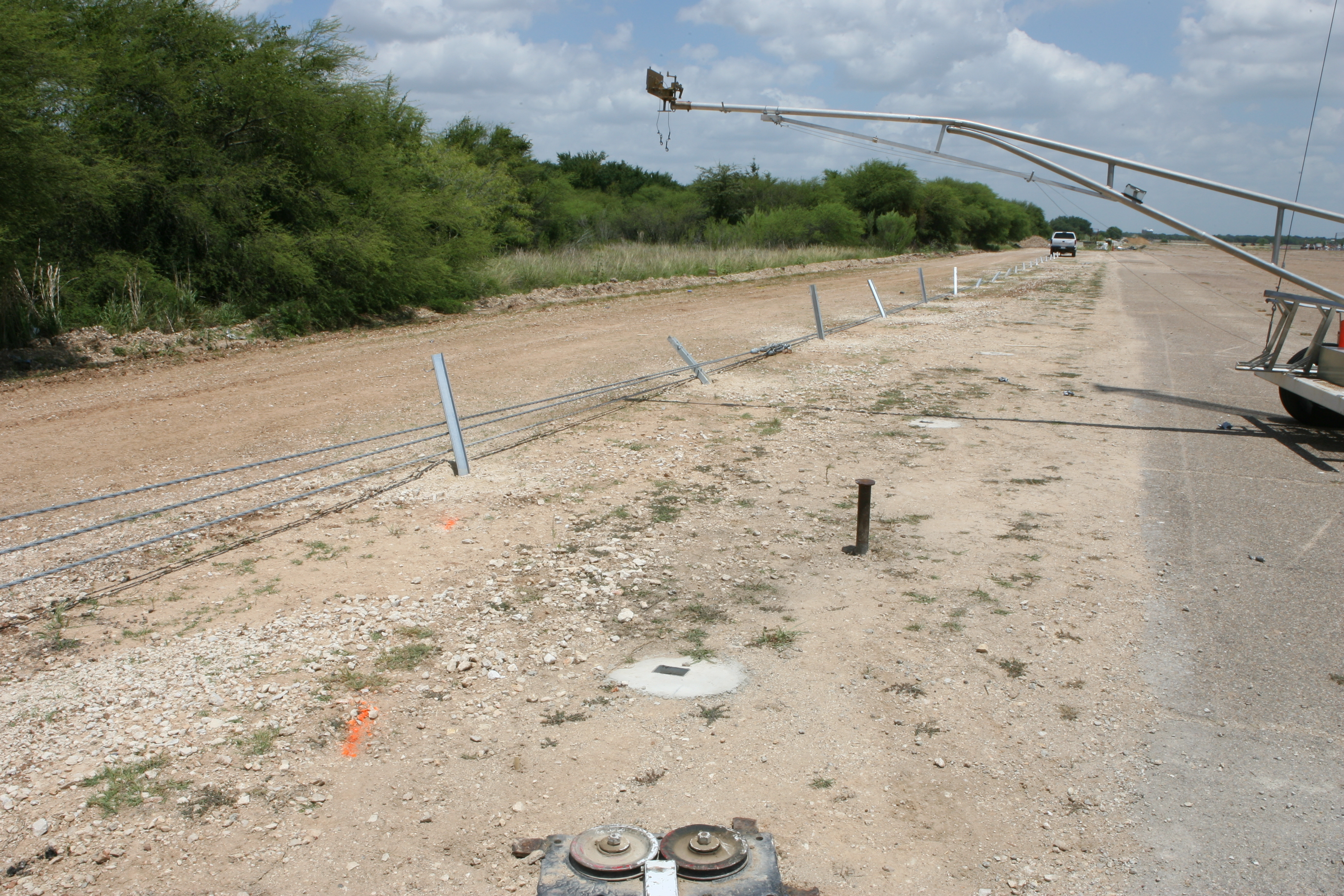 |
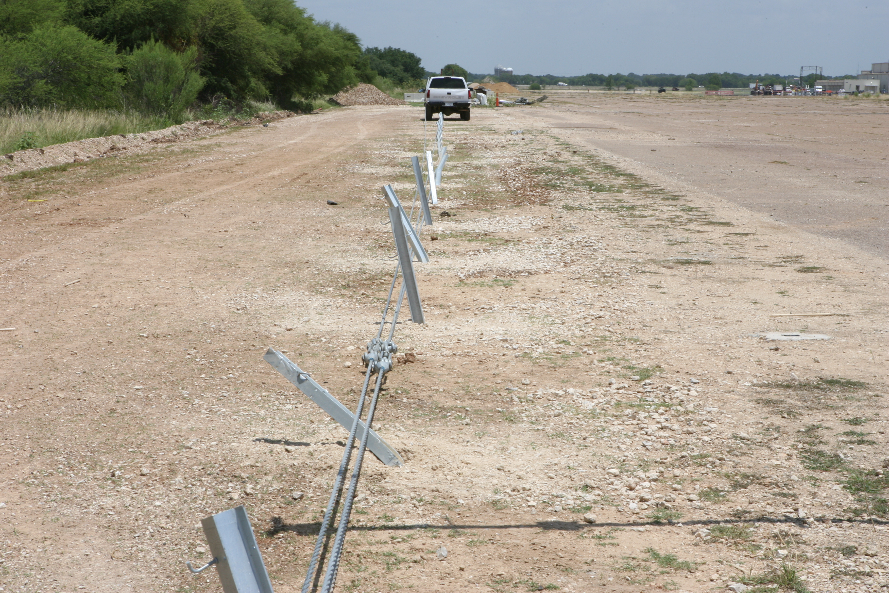
| Barrier After Test | |
 |
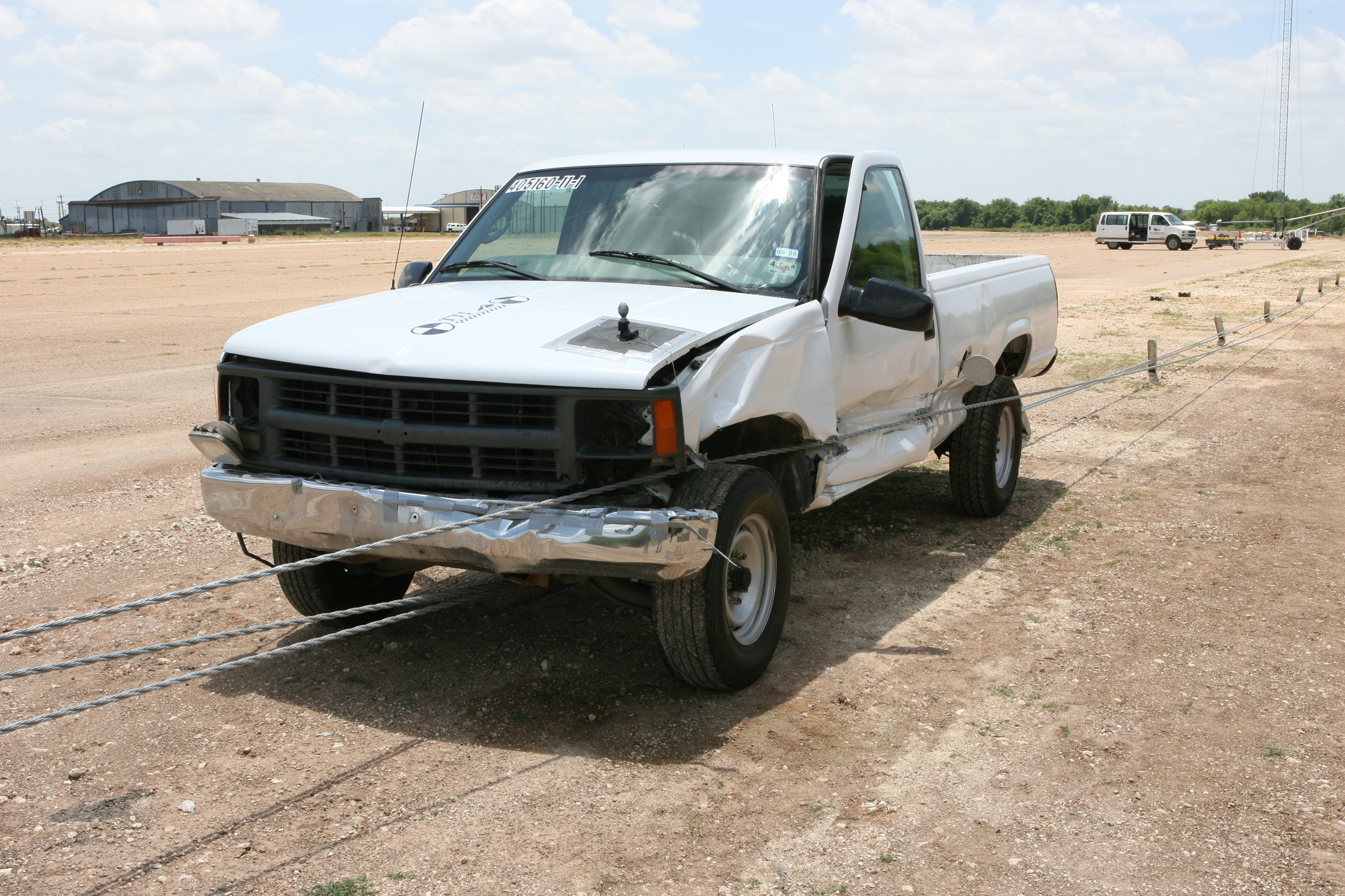 |
| Vehicle Before and After Test | |
If accident history indicates a high propensity for cross-over type accidents on an installed low tension system, conversion to a high tension system could improve its ability to contain and redirect secondary impacts that occur before maintenance crews repair impacted barriers. This process will require the low tension terminals be replaced with FHWA accepted high tension terminals. The spring compensators will need to be removed and the terminations should be replaced.
The retrofitted system has met the criteria for NCHRP Report 350 TL-3. However, the large size and mass of the Epoxy Socket termination have raised questions about performance when impacted by a smaller vehicle. It is yet to be determined whether the large Epoxy Socket terminations would lead to excessive damage and/or snagging of a small car. Therefore, it is recommended that a small car test be performed on this system. The Field Swage termination should meet all criteria for acceptance under TL-3. A number of similar factory applied swage fittings have performed acceptably with both cars and pickups.
Preventing Underrides
Due to recent concerns over underriding barrier events, the pooled fund sponsoring states requested that TTI evaluate adding a fourth cable during the retrofit process to reduce the risk of a vehicle underriding the retrofitted barrier.
A review of current vehicle trajectory and cable heights research was performed to help in evaluating the height of the additional fourth cable. Data from National Crash Analysis Center (NCAC) and Midwest Roadside Safety Facility (MwRSF) indicate the lower additional wire rope should not be placed higher than 13.5 inches above grade.
TTI recommends if a fourth cable is to be added, it should have a height of 13.5 inches above ground to reduce underriding events.
Retrofit Manuals
Two detailed retrofit manuals were developed for retrofitting existing low-tension three wire rope systems. The first manual details the conversion process to a three wire rope high-tension system. The second manual details the conversion process to a four wire rope high-tension system. Each retrofit manual presents step by step instructions and photos targeting maintenance personnel and installation contractors.
Real-Time Video
High-Speed Gut Video
High-Speed Rear of Rail Video
High-Speed Overhead Video
High-Speed Rear of rail and vehicle Video
High-Speed Frontal (long shot) Video
2017-04-07