MASH Test 3-21 of Free-Standing to Anchored PCB System on Asphalt (TTI-622421, T1969-A8)

<<back to search

TTI Research Supervisor:
Nauman M. Sheikh, P.E.
Research Engineer
Texas A&M Transportation Institute
Texas A&M University System
TAMU 3135, College Station, Texas,77843-3135
(979) 317-2695
[email protected] 
  Pooled Fund Technical Representative:
Bob Meline, P.E.
California Department of Transportation
Structural Materials Building, Rm 422
5900 Folsom Blvd.
Sacramento, CA 95819
(916) 227-7031
[email protected]

Background (and Problem Statement)

With research sponsorship from California Department of Transportation (Caltrans), Texas A&M Transportation Institute (TTI) developed anchored portable concrete barrier (PCB) systems that were comprised of 32-inch tall, 12-ft long, F-shape profile concrete barrier segments (1). These segments were anchored to underlying pavement using vertical anchoring pins or epoxy anchor bolts. The following four anchored barrier designs were developed. 1. PCB anchored on asphalt pavement as a roadside barrier with vertical anchor pins at three locations on the impact-side. 2. PCB anchored on concrete pavement as a roadside barrier with epoxy anchors at the three locations on the impact-side. 3. PCB anchored on asphalt as a median barrier with vertical anchor pins located only at the four corners of each segment. 4. PCB anchored on concrete pavement in the four corner anchor positions with shallow embedment epoxy anchors, which can be used as a median or a roadside barrier. The designs were successfully crash tested in accordance with American Association of State Highway and Transportation Official’s (AASHTO) Manual for Assessing Safety Hardware (MASH) Test 3-11 evaluation criteria for longitudinal barriers (2). All designs successfully passed the evaluation criteria. The anchored PCB systems were determined to be MASH Test Level 3 (TL-3) compliant. In this past research, TTI also developed a design of a transition from free-standing F-shape PCB to F-shape PCB anchored on asphalt in a median barrier configuration. The design was evaluated using finite element (FE) simulation analysis, but crash testing was not performed. Caltrans now desires to evaluate this transition design through full-scale crash testing.
 

Objective

Objective of this project is to perform MASH Test 3-21 of freestanding-to-anchored CAL F-23 barrier on asphalt concrete (AC) in the median configuration. This test will evaluate the transition design previously developed by TTI through simulation analysis.

Benefits

Successful completion of this project will provide a transition design that allows connecting Caltrans’ free-standing PCB system to anchored median PCB system in a MASH compliant manner.

Products

The TTI research team will provide composite video and photographic documentation of the crash tests and a final report documenting the research and testing performed. If applicable, TTI will provide documentation needed to request FHWA’s acceptance of the transition system for use on the National Highway System. The TTI research team will further provide drawings of the barrier systems and of each of the components.

Work Plan

The work plan for this research includes the following tasks.

Task 1: Construction, Demolition, and Site Restoration
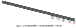
In this task, TTI research team will construct the test installation of the free-standing PCB to median anchored PCB on asphalt. TTI research team will first develop the barrier and system drawings and present to Caltrans for approval. Once Caltrans has approved barrier segment and test installation drawings, TTI research team will construct the needed barrier segments and other hardware, either inhouse, or via third party vendors. The test installation will be comprised of the same barrier segment and other connecting and anchoring hardware that were tested under previous project (1). The transition design will be the same as what was determined through previously performed simulation analysis. Figure 1 shows the schematic of this system. The test installation will be comprised of 13 barrier segments. The segments will be 32-inch tall, 12-ft long, and have the F-shape profile. Four of the barrier segments will be anchored on an asphalt pavement in a median configuration, i.e., each segment will be anchored with four anchoring pins – one installed in each corner of the barrier segment. The transition barrier segment will be the same F-shape barrier segment as the rest of the system. This segment, however, will only be anchored using two anchoring pins – one installed in each corner hole directly adjacent to the anchored PCB system. There will be 8 freestanding/unanchored segments that will be attached to the transition barrier segment. The asphalt pad underneath the anchored PCB segments will be 4 inches thick and will be constructed on top of compacted soil. After the crash test has been performed, the research team will demolish the test installation, dispose the PCB barriers and associated hardware, and restore the test site to original conditions.

Task 2: MASH Test 3-21
The TTI research team will perform full-scale crash testing of the transition system in accordance with the MASH Test 3-21 evaluation criteria. TTI has an International Standards Organization (ISO) 17025-accredited laboratory. TTI research team will procure and prepare the test vehicle for crash testing by installing the instrumentation necessary to record dynamic testing data, such as vehicle acceleration and rotation, and the instrumentation necessary to guide the vehicle into the test installation at high speeds and stop it after the impact. TTI research team will record the crash tests using high-speed digital cameras and ascertain that the vehicle impacts the barrier at the MASH specified impact speed and angle. TTI research team will analyze the high-speed test videos to determine the barrier and transition system’s dynamic deflection during the crash test. The barrier will be impacted by a 5,000-lb pickup truck at an impact speed and angle of 62 mph and 25 degrees, respectively.

Task 3: Final Report
TTI research team will prepare a final report documenting details of the test performed under this research. The report will also include results of the crash test and, if applicable, relevant implementation guidance. The research team will provide a draft of the final report to Caltrans for review, prior to finalizing the report.

Time Schedule

Started: April 2025
Time frame: 10 months

April 9, 2025