
| TTI Research Supervisor: Roger P. Bligh, Ph.D., P.E. Senior Research Engineer Texas A&M Transportation Institute Texas A&M University System TAMU 3135, College Station, Texas, 77843-3135 (979)317-2703 [email protected] |
Pooled Fund Technical Representative: |
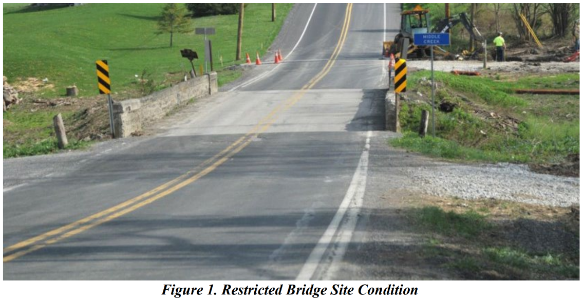
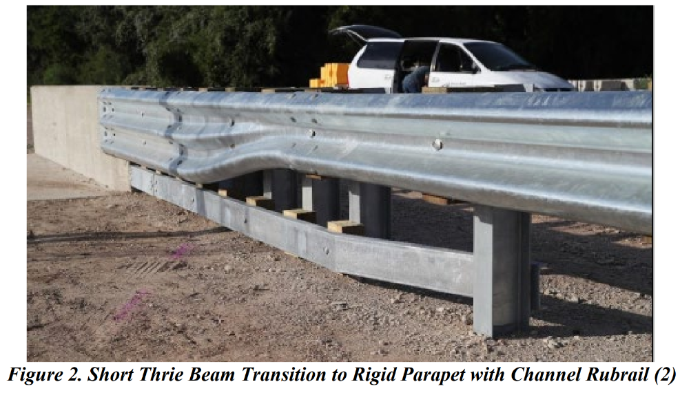
One of the most common forms of transitions is an approach guardrail transition to a bridge rail. Such stiffness transitions are used to transition the stiffness from the more flexible approach guardrail to the stiffer barrier bridge rail. The stiffness is transitioned through the use of stiffer rail elements (e.g., nested rails) and changes to post size, embedment depth, and/or spacing. Proper transitioning of the stiffness mitigates barrier pocketing and vehicle snagging on the end of the stiffer barrier system. There are different configurations of approach guardrail transition systems. One of the more common configurations uses nested thrie beam rail and reduced post spacing adjacent to the bridge rail end. Such transitions are typically 18 ft-9 in to 25 ft in length. Site conditions, such as intersecting roads or driveways in proximity to the bridge end, can restrict the distance available to accommodate barrier length of need and make a shortened transition system desirable (see Figure 1). Under a project sponsored by the Roadside Safety Pooled Fund, a shortened approach transition, shown in Figure 2, was successfully developed and crash tested in accordance with the American Association of State Highway and Transportation Officials (AASHTO) Manual for Assessing Safety Hardware (MASH) Test Level 3 (TL-3) criteria (1, 2). The transition system uses a 6 ft-3 in section of nested thrie beam and a 6 ft-3 in asymmetric thrie beam-to-W-beam transition section with reduced post spacing. The transition further incorporates a lower rubrail element to help mitigate potential for vehicle snagging on the end of the rigid concrete bridge parapet. The system provides state departments of transportation (DOTs) with a desirable solution when limited space exists at the end of bridges.
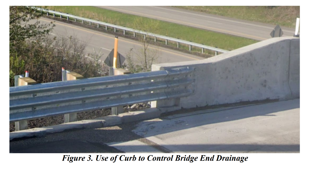
When solid bridge rails or metal bridge rails mounted on concrete parapets are used, drainage occurs at the bridge ends. To avoid erosion around the bridge wing walls, the steep side slopes that are often adjacent to a bridge end, and the transition posts, state DOTs often control the location of the bridge end drainage using curb elements that abut the end of the bridge rail, such as shown in Figure 3. Such curbs are typically 4 to 6 inches in height and may have different shapes.
When curbs are used at bridge ends, the transition must be designed to incorporate the curb element. In certain scenarios, the presence of a curb element may help reduce bridge end snagging potential and eliminate the need for a rubrail below the primary transition rail element. The goal of this research is to expand the use and functionality of the previously developed shortened thrie beam transition (2) by incorporating a curb element to accommodate bridge end drainage. A MASH TL-3 transition of this type would be useful in areas with limited space and with a curb to accommodate bridge end drainage.