
Final Report Link: WSDOT Pin & Loop Barrier with Drainage Slots – Phase I
Link to: Phase II
| TTI Research Supervisor: William F. Williams, P.E. Texas Transportation Institute Texas A&M University System TAMU 3135 College Station, Texas 77843-3135 (979) 862-2297 [email protected] |
Pooled Fund Technical Representative: John P. Donahue Washington State Department of Transportation Transportation Building 310 Maple Park Avenue P.O. Box 47329 Olympia, Washington 98504-7329 [email protected] |
Simple engineering analyses was performed on the Washington pin and loop barrier to improve the strength for the barrier section from crash impact loading. To further evaluate the free standing precast single slope concrete barrier, a finite element analysis was then performed to determine the maximum lateral deflection of the barrier due to impact from a pickup truck vehicle under American Association of State Highway and Transportation Officials (AASHTO) Manual for Assessing Safety Hardware (MASH) test level 3 conditions. Additional simulations were performed to determine the potential of wheel snagging for the small passenger vehicle due to the presence of the drainage scupper.
After these analyses were completed, a full-scale crash test was then performed to assess the performance of the Washington DOT pin and loop concrete barrier with drainage slots according to the safety-performance evaluation guidelines included in MASH. The crash test was in accordance with Test Level 3 (TL-3) of MASH, and involves the 2270P vehicle (a 5000 lb, 1/2 ton, Quad Cab Pickup).
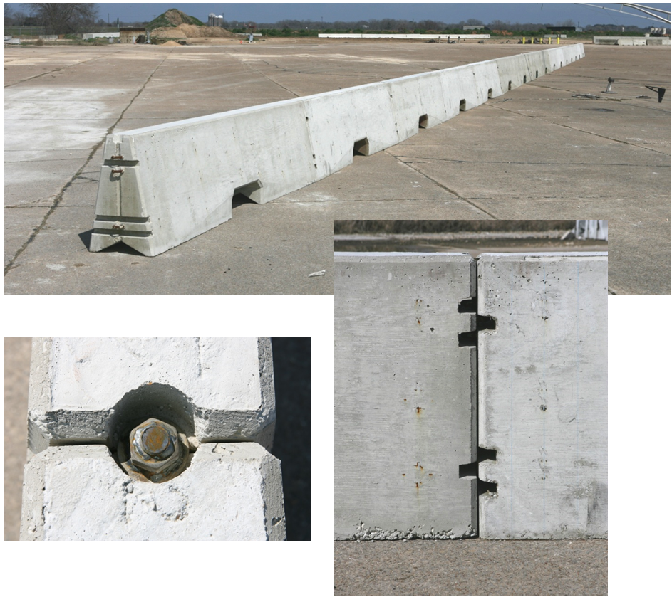
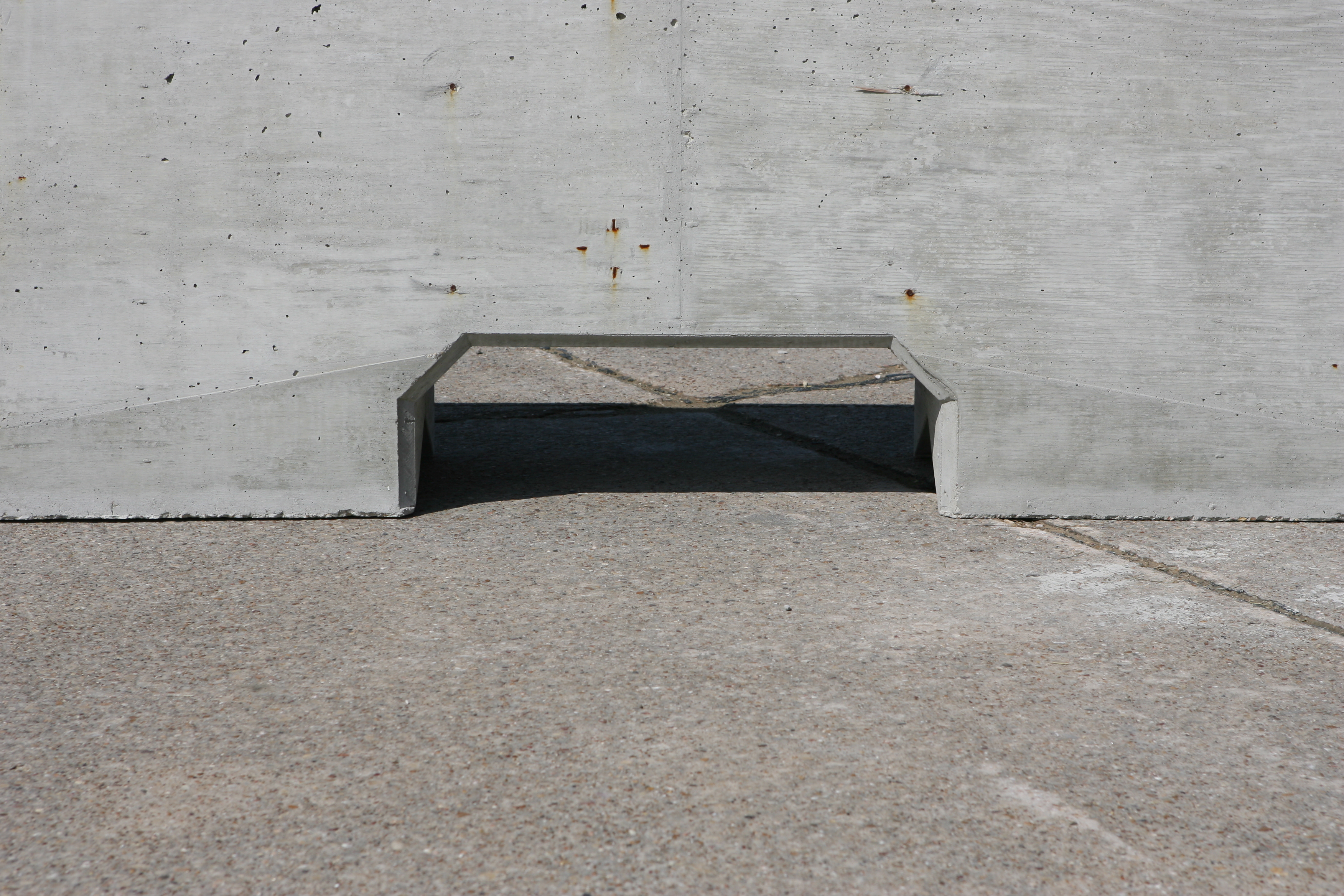
Figure 1. Photos of the Pin & Loop Barrier System.
To evaluate the free standing precast single slope concrete barrier, a full-scale finite element model of the barrier was developed. Finite element analysis was performed to determine the maximum lateral deflection of the barrier due to impact from a pickup truck vehicle under MASH test level 3 conditions. Additional simulations were performed to determine the potential of wheel snagging for the small passenger vehicle due to the presence of the drainage scupper.
Finite element analysis was performed using LS-DYNA software. LS-DYNA is a general-purpose, explicit finite element code used to analyze the nonlinear dynamic response of three-dimensional structures.
The finite element model was comprised of 12 concrete barrier segments that were 12.5‑ft in length. The finite element mesh of the barrier model, shown in Figure 2, was comprised of solid elements with rigid material representation. The barrier segment material was assigned the mass density of reinforced concrete, which made the total mass of the barrier model equivalent to the actual barrier.
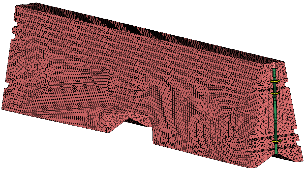
Figure 2. Finite Element Model of the Barrier Segment and Pin & Loop Connection.
Adjacent barrier segments were connected using a pin-and-loop type connection comprised of shell and beam elements with elastic-plastic material representation. Failure of the barrier concrete was not incorporated in the model due to the lack of robust concrete damage models. If significant concrete fracture and spalling occurs at the ends of one or more barrier segments during an actual impact, additional joint rotation can occur. This in turn can increase barrier deflection and vehicle instability and climb. Therefore, the results of the simulation represented a lower bound estimate of the overall barrier system deflection. With these aspects of the model understood, valuable design and performance information can be gleaned from the simulation results.
The first simulation was performed with a 5000-lb pickup truck vehicle model. The pickup truck model used in the simulations was developed by the National Crash Analysis Center (NCAC) with funding from Federal Highway Administration (FHWA) and the National Highway Traffic Safety Administration (NHTSA).
The full system model of the barrier is shown in Figure 3. The simulated impact conditions correspond to Test Designation 3-11 of MASH. This test involves a 5000-lb pickup truck impacting the barrier at a speed of 62 mi/h and an angle of 25 degrees. This test is considered to be the critical test for evaluating the structural integrity of the barrier and the maximum dynamic deflection due to impact. The vehicle model impacted the barrier system 4 ft upstream of the joint between the fifth and the sixth barrier segment as shown in Figure 3. Simulation results from the modeling effort was favorable with respect to MASH 3-11 Specifications.
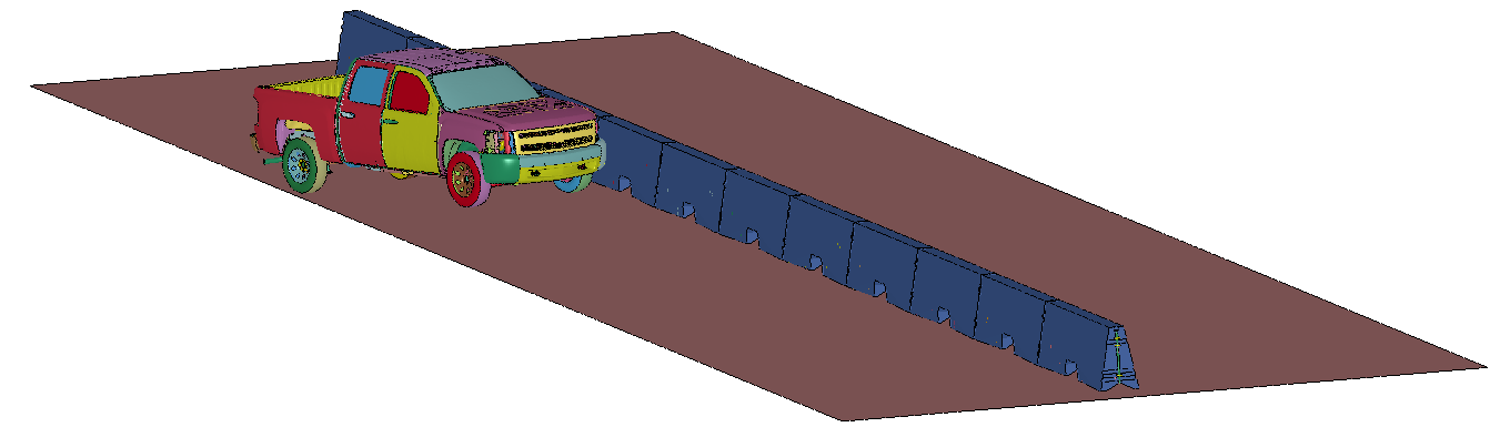
Figure 3. System Model.
A full-scale crash test was performed for this project. Details of the test installation constructed are shown in Figure 4.
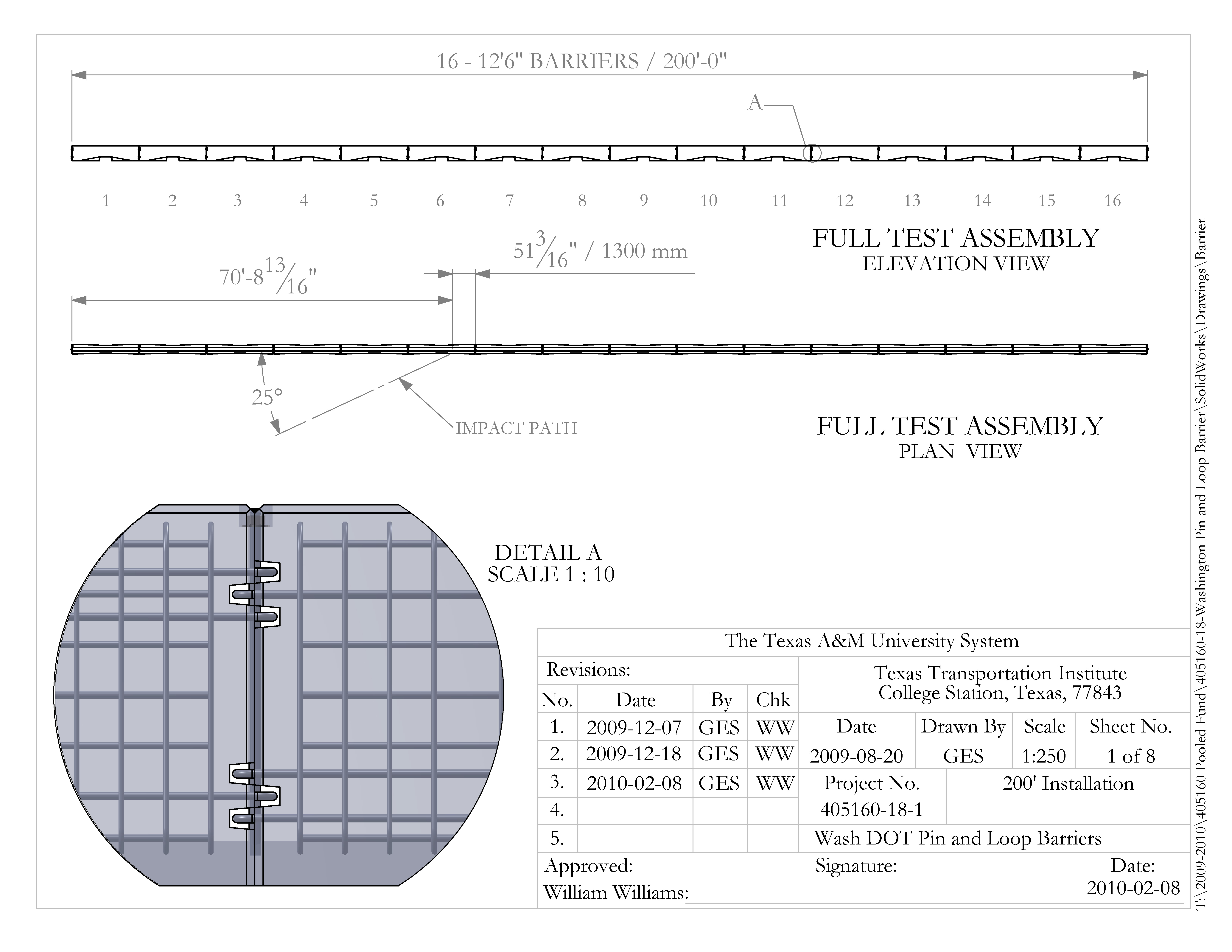
Figure 4. Details of Test Installation.
The Washington Pin and Loop Barrier system tested for this project consisted of precast concrete barrier segments that were 12 ft-6 inch in length and 34 inches in height. The barrier segment was 8 inches wide at the top and 21 inches wide at the base with a uniform single slope surface on each side face of the barrier. The barrier was constructed with a 4-inch high by 15‑inch wide “V” shaped drainage slot that was continuous along the entire length of the barrier segment. In addition to this longitudinal drainage slot, a transverse drainage scupper opening was constructed at the center of the barrier segment. The drainage scupper opening was 9 inches high by 28 inches in width.
Based on the results from the crash test, these drainage slots and scupper opening did not appear in any way to adversely affect the crash performance of the barrier system. Soon after impact, the vehicle rolled over as it was being redirected and exiting away from the barrier system. Due to rollover and the occupant compartment deformation caused by the rollover, the Washington DOT pin and loop concrete barrier with drainage slots and scupper opening did not perform acceptably according to the evaluation criteria for MASH test 3-11.
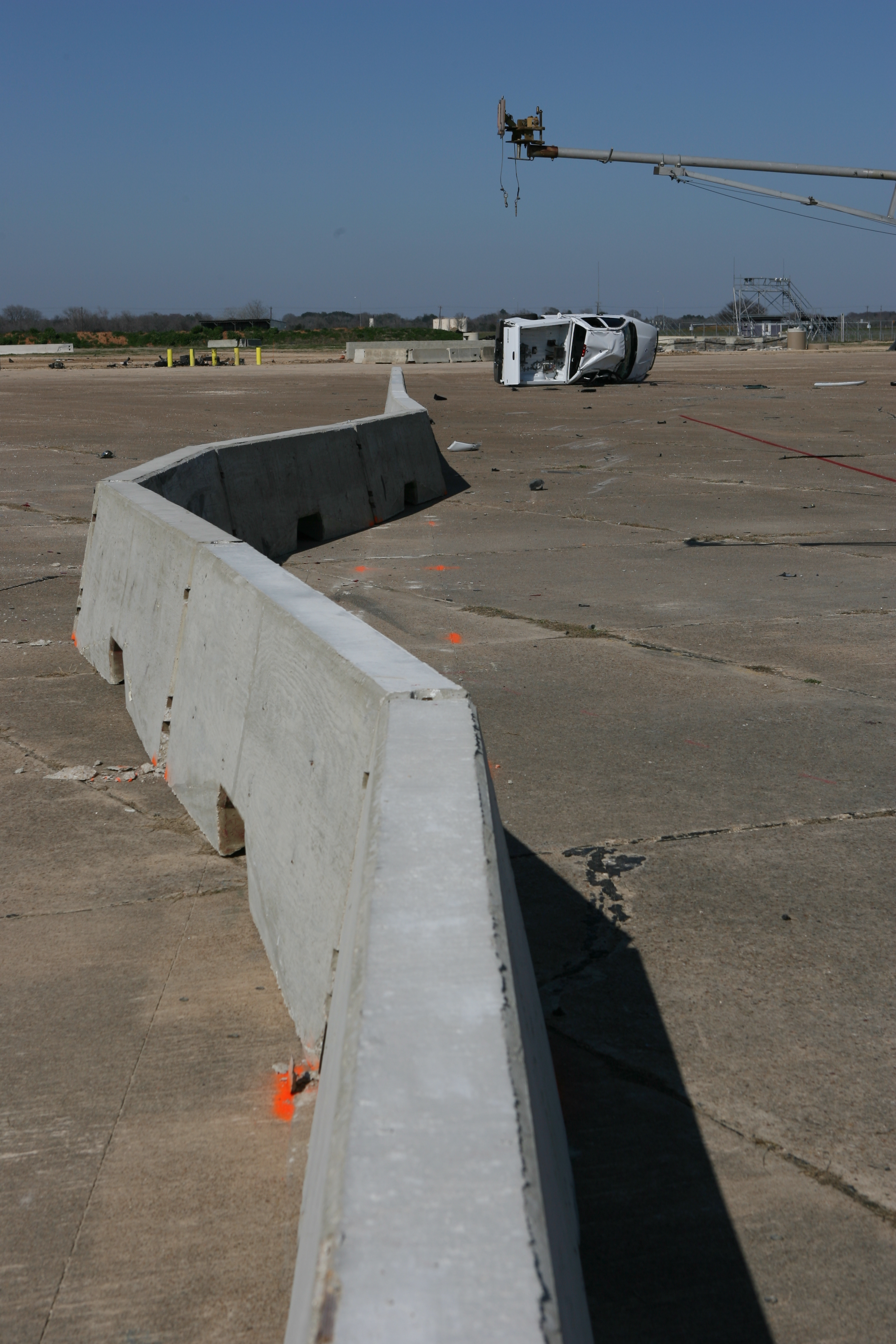
Figure 5. Barrier and Test Vehicle after Crash Test.
2017-04-06