
Links to other Phases:
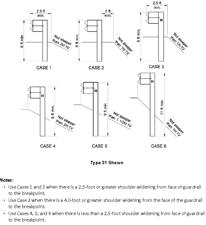
The American Association of State Highway and Transportation Officials (AASHTO) Roadside Design Guide recommends that guardrail be installed with the back edges of the guardrail post being 2 ft from a slope break. In many mountainous areas or in locations with tight environmental controls, this width is difficulty to provide. As a result, designers often have to make a trade-off between reduced shoulder width and a less than optimal guardrail placement. The Washington State Department of Transportation (WSDOT) Design Manual provides for the placement of the guardrail post closer to or on slopes as steep as 1H:1V, as illustrated in Figure 1.
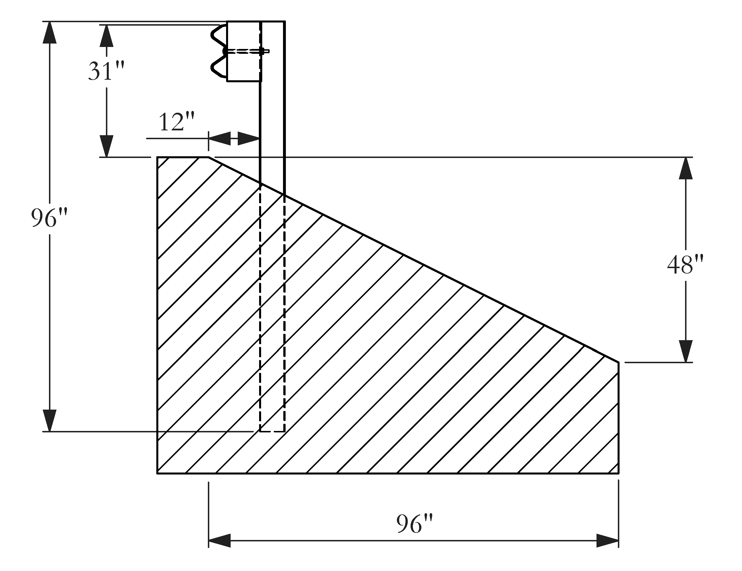
During the preceding phase of this research, Texas A&M Transportation Institute (TTI) researchers conducted two full-scale crash tests of a 31-inch high guardrail system placed on 2H:1V slope. The posts were placed 1 ft from the slope break such that the face of the guardrail was aligned with the slope break, as shown in Figure 2.
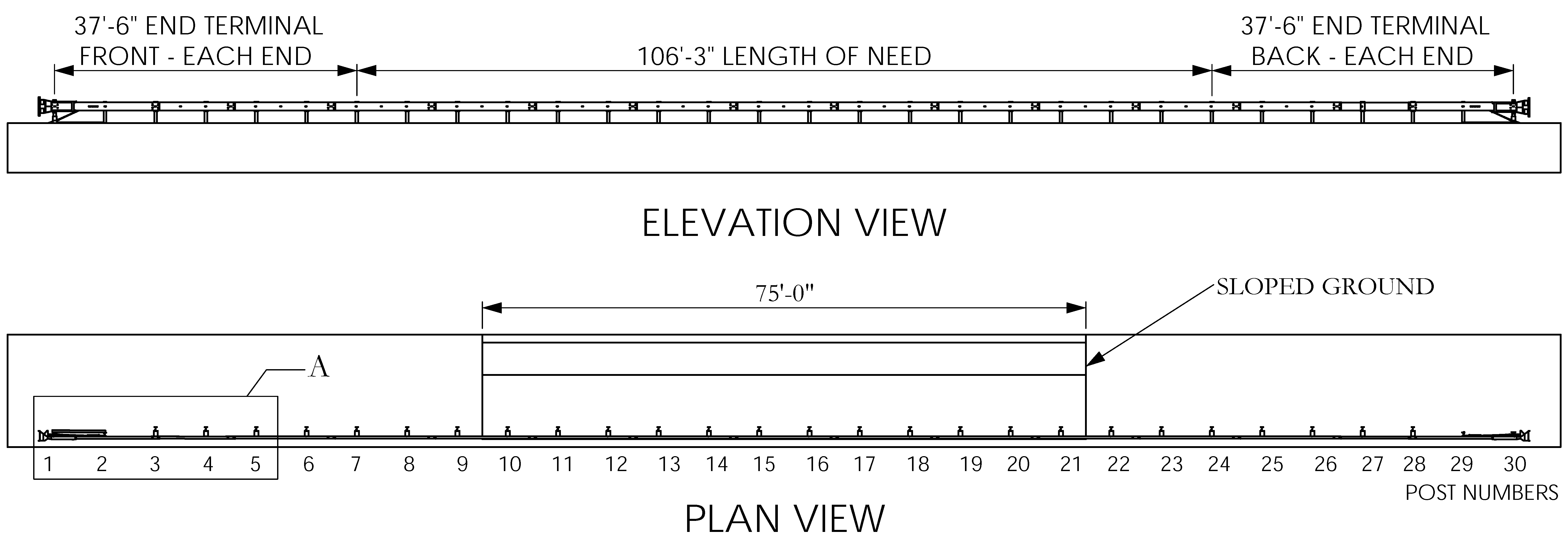
The guardrail on slope system test installation had a total length of 181.25 ft. The system was comprised of a 106.25-ft length of need section and a 37.5-ft long ET PLUS terminal on each end. The 12-gauge W-beam was mounted on W6×8.5 steel posts. The guardrail height was 31 inches above the flat terrain. A 2H:1V sloped ditch was excavated behind the rail to represent the slope terrain. The ditch was centered along the installation length and was 75 ft long and 12 ft wide. An overview of this system installation is shown in Figure 3. Standard size 6 inch × 8 inch × 14 inch routed wood blockouts were used in the length of need section.
Two AASHTO Manual for Assessing Safety Hardware (MASH) crash tests were performed.
The test vehicle was successfully redirected by the guardrail system in each test. The test evaluation metrics were all within the limit of MASH test evaluation metrics. Hence, both tests passed MASH test evaluation criteria. Sequential images of both tests are shown in Figure 4.
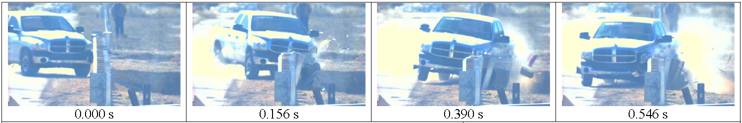
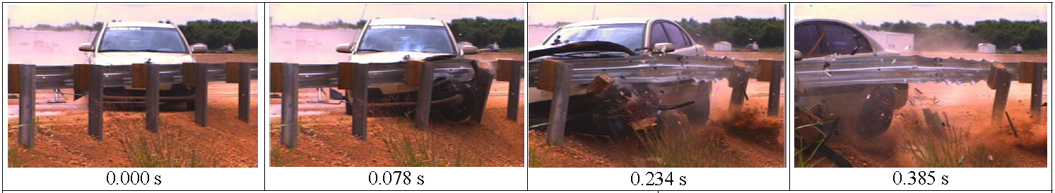
Figure 4. Sequential Photos of MASH 3-11 and MASH 3-10.
The objective of this study is to identify an acceptable method for installing standard strong-post W-beam [Modified G4(1S)] with the face of the rail aligned with the break point of a 1J:1V slope.
A guardrail system in which the face of the rail is aligned with the slope break will provide significant savings in shoulder width in mountainous areas as well as other locations that have very restrictive space.
TTI will provide a report documenting the research process and the recommendation for future development of the full evaluation through crash testing.
Implementation plans depend on the outcome of the crash testing to be defined for potential Phase IV of this project.
The researchers will perform three bogie tests of posts placed on 1H:1V slope terrain. The test matrix will be drawn from three of the following post lengths:
Although 8-ft posts were successfully used in the guardrail installation on the 2H:1V slope described earlier, the performance of 8-ft posts was not quantified when placed adjacent to a steeper 1H:1V slope.
All three tests will be conducted using the 1800-lb crushable nose bogie at approximately 22 mi/h, to represent the side impact energy imparted by an errant vehicle.
The research team will start by testing the 10-ft post first and compare its post deflection and soil movement patterns to those observed in the earlier battery of bogie tests and the aforementioned crash tests. If the post deflection pattern is stiffer that the referenced experiments/tests, the research team will test the 9-ft and 8-ft posts. Otherwise, the research team will test the 9-ft and the 11-ft posts.
The research team will identify two promising post lengths for further evaluation. the identification process consists of defining the deflection of the posts and compare their soil interaction against each other and the existing crash test. Then, the research team will simulate these candidate post lengths to calibrate the new sloped soil model. Finally, the research team will simulate needed MASH crash tests to further quantify the post’s performance under simulated vehicular impact conditions.
The research team may need to refine the vehicle and guardrail system models, if needed. Hence, this simulation process is iterative in nature.
Finally, the results of these simulations will be summarized and submitted to the state pooled fund technical representative along with a recommendation design for further evaluation through full-scale crash testing during a subsequent phase of this project.
| TTI Research Supervisor: Akram Abu-Odeh, Ph.D. Research Scientist Texas A&M Transportation Institute TAMU 3135 College Station, Texas 77843-3135 (979) 862-3379 [email protected] |
Pooled Fund Technical Representative: Jeff K. Petterson, P.E. Roadside Safety Engineer Washington State Department of Transportation P.O. Box 47329 Olympia, WA 98504-7329 (360)705-7246 [email protected] |