
Final Report Link: Evaluation of Existing T-Intersection Guardrail Systems for Equivalency with NCHRP Report 350 TL-2 Test Conditions – August 2010
| TTI Research Supervisor: Akram Abu-Odeh, Ph.D. Texas Transportation Institute Texas A&M University System TAMU 3135 College Station, Texas 77843-3135 (979) 862-3379 [email protected] |
Pooled Fund Technical Representative: Paul Fossier Louisiana Department of Transportation P.O. Box 94245 1201 Capitol Access Road Baton Rouge, LA 70804-9245 (225)379-1323 [email protected] |
When a road or driveway intersects a highway with certain restrictive features (bridge rail, culvert, …etc), it is difficult to fit the proper guardrail length (transition, length-of-need guardrail, and end treatment) along the primary roadway. Site constraints such as private driveways, state roads, and parish or county roads may intersect the primary road and not allow the placement of a properly designed guardrail length of need.
In these cases, alternatives are to shorten the designed guardrail length, provide a curved or T-intersection guardrail design, or relocate the constraint blocking placement of the guardrail. This curved guardrail system is usually known as a short radius guardrail.
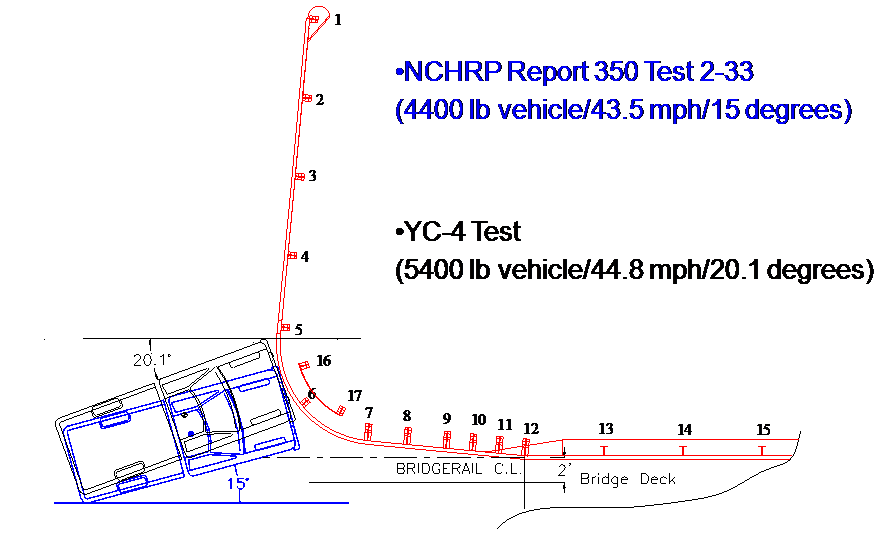
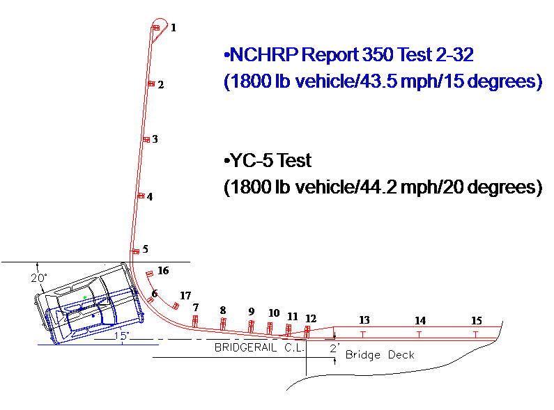
This study was undertaken to investigate the performance of previously tested T-intersection guardrail systems to determine if some of these previously tested T-intersection guardrail systems would meet NCHRP Report 350 TL-2 criteria. The evaluations performed in this study indicate that the Yuma County T-intersection guardrail design meets NCHRP Report 350 TL-2 criteria. The study approach consists of (a) determination of an appropriate NCHRP Report 350 TL-2 test matrix for short radius guardrail, (b) a review of the crash tests performed on a T-intersection guardrail treatment developed for Yuma County, Arizona, (c) a comparison of Yuma County tests with the NCHRP Report 350 tests, and (d) an investigation of the energy dissipation contribution of the free standing CRT post that were part of the original design. As a result of this research, the following conclusions are made: Yuma County tests have either similar or higher impact severity in terms of velocity and vehicular weight than corresponding NCHRP Report 350 TL-2 tests. Therefore, conditions of NCHRP Report 350 TL-2 tests were attained or exceeded by the Yuma County tests. The dissipated energy associated with fracturing the two free standing CRT posts is not significant enough to affect the performance of the system. Hence, the recommended T-intersection system does not incorporate the two free standing CRT posts behind the curved section.
 |
 |
Minimum T-Intersection Details
A recommended NCHRP Report 350 TL-2 T-intersection system (see next page) is a 27 inch high W-beam rail system. The nose section of this T‑intersection system consists of a 12.5 ft curved W- beam segment having an 8 ft radius. The curved section is attached to a straight W‑beam section on the secondary road using common W-beam splicing details. The secondary road W-beam should have a 25 ft minimum length and should be terminated with a positive anchor. Five CRT posts, spaced at 6.25 ft, are placed along the curved section and secondary road section. On the primary road direction, the curved section is as attached to a transition to the bridge rail. The transition in stiffness is achieved by using a reduced post spacing, increasing post size, and using a MC 8 × 22.8 structural steel channel behind a the W-beam adjacent to the bridge rail.
Acceptable System Changes
Design changes to the aforementioned system can be made provided the impact performance is not affected. The researchers conclude the following modifications are acceptable:
FHWA issued an acceptance letter (HSSI/B-209) on November 10, 2010 for this T-Intersection guardrail system.

T-Intersection-Acceptance Letter B209_111710
2017-09-18